Heat Pump Components: What Each Part Does
A heat pump is an electrically driven heating and cooling system that transfers thermal energy from outdoor air, the ground, groundwater or another low-temperature source into a building. The essential answer is simple: the vapour-compression heat pumps discussed here use an evaporator, compressor, condenser, expansion valve and refrigerant.
A complete installation includes more than the sealed refrigerant circuit. Source equipment gathers environmental heat, hydraulic equipment moves water, controls coordinate operation, and the building’s emitters release heat. The exact component package changes with the heat source, output, domestic-hot-water design and whether equipment is integrated or installed separately.


What are the main components of a heat pump?
A heat pump has four core refrigeration components: an evaporator, compressor, condenser and expansion valve. A complete heating system also needs refrigerant, a heat-source interface, circulation pumps, controls, sensors, electrical equipment and components that distribute heat through the building safely.
The following table separates the sealed refrigeration machine from the equipment around it.
| Component or group | Primary function | Typical position |
|---|---|---|
| Heat-source interface | Collects thermal energy from air, ground, groundwater or a shared low-temperature network | Outdoors, underground, in wells or in a source plant |
| Evaporator | Transfers source heat into the refrigerant, causing the refrigerant to evaporate | Refrigerant circuit |
| Compressor | Raises refrigerant pressure and temperature; it is the main electrical load during normal compressor operation | Refrigerant circuit |
| Condenser | Transfers refrigerant heat to the building’s water circuit, causing the refrigerant to condense | Refrigerant circuit |
| Expansion valve | Reduces refrigerant pressure and meters flow before the evaporator | Refrigerant circuit |
| Refrigerant and pipework | Carry thermal energy between the four core components | Sealed refrigerant circuit |
| Hydraulics and heat delivery | Circulate water, manage pressure, store heat when needed and deliver it to rooms or domestic hot water | Indoor unit, plant room and building |
| Controls and electrical equipment | Measure conditions, command components, protect circuits and connect energy-management functions | Heat-pump unit, electrical distribution and building controls |
A refrigerant is a working fluid selected to absorb and release heat at useful temperatures. Refrigerants operate inside a sealed circuit; product-specific safety, servicing and end-of-life requirements depend on the refrigerant and equipment design.
The European Heat Pump Association identifies the evaporator, compressor, condenser and expansion valve as the central parts in the heat-transfer sequence.
How do the four core refrigeration components work together?
Together, the evaporator, compressor, condenser and expansion valve keep refrigerant circulating through changing pressure and temperature conditions. The evaporator collects environmental heat; compression raises temperature; the condenser delivers useful heat; and expansion prepares refrigerant to absorb heat in another circuit.
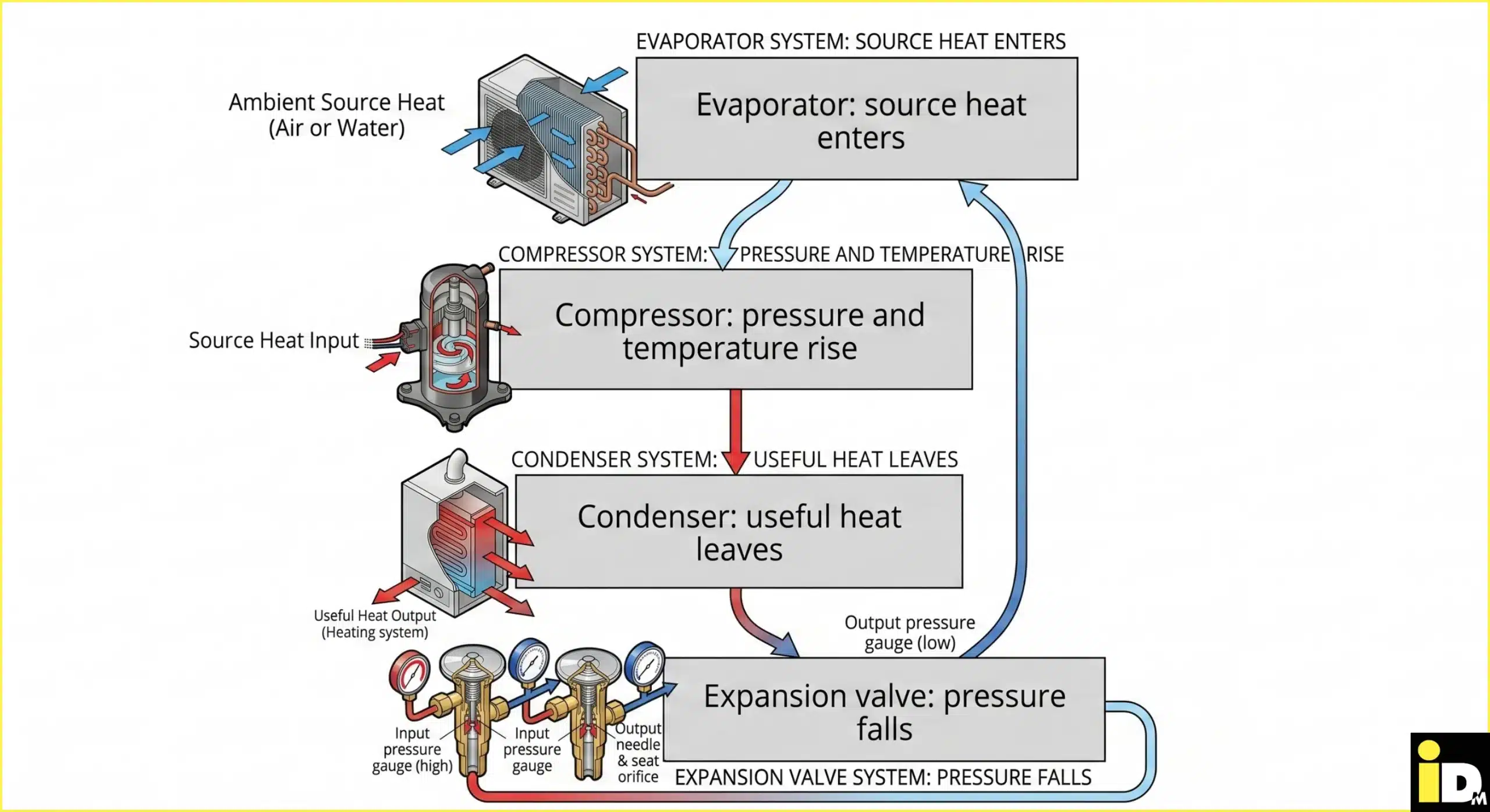
- The evaporator is a heat exchanger that absorbs energy from the selected source and transfers it to the refrigerant.
- The compressor uses electricity to compress refrigerant vapour, raising its pressure and temperature.
- The condenser is a second heat exchanger that transfers energy from the hot refrigerant to the building’s water circuit.
- The expansion valve meters refrigerant into the evaporator at lower pressure, completing the component sequence.
Heat exchangers keep the refrigerant physically separate from source fluid and heating water while allowing energy to pass through their surfaces. A reversing valve is an additional component in reversible systems; it changes refrigerant-flow direction so the machine can provide active cooling.
Which source-side components change by heat pump type?
Source-side components depend on where the heat originates. Air-source systems use an outdoor heat exchanger and fan; ground-source systems use buried collectors or boreholes with a circulating fluid; groundwater systems require designed wells, pumps and water-side protection for reliable operation.
The source side is the installation zone that collects environmental energy before the refrigerant circuit raises its temperature.
| Heat-pump type | Heat source | Source-side components | Site implication |
|---|---|---|---|
| Air-to-water | Outdoor air | Finned heat exchanger, fan, condensate path, protective casing and sensors | Needs suitable outdoor placement, airflow and sound planning |
| Brine-to-water | Ground | Horizontal collector or borehole, brine fluid, circulation pump, manifold, expansion and safety equipment | Needs ground design and project-specific approvals |
| Water-to-water | Groundwater | Abstraction and return wells, source pump, filtration and, where design requires it, an intermediate heat exchanger | Needs water-quality assessment and project-specific approvals |
| Apartment or ambient-loop system | Shared low-temperature water network | Central source plant, distribution loop, pumps, metering and dwelling-level heat-pump units | Separates central source production from apartment-level heat delivery |
Brine is a freeze-protected heat-transfer fluid that circulates through a ground collector or borehole. Groundwater systems instead move water from an abstraction well through the source arrangement and return it according to the approved design.
Air-source equipment also needs a safe condensate route. Moisture can freeze on the outdoor heat exchanger during cold, humid conditions, so the component layout must permit drainage and automatic defrosting without creating unsafe ice around the unit.
Which heating-system components sit outside the refrigerant circuit?
The refrigerant circuit transfers energy, while the hydraulic circuit moves heated water to rooms and domestic hot-water equipment. Depending on system design, this side contains circulation pumps, valves, an expansion vessel, safety devices, a buffer tank, cylinder and heat emitters.
The hydraulic circuit is the water-filled network between the condenser and the building’s heating or hot-water equipment. Its design determines flow, pressure, temperature distribution and how the heat pump interacts with multiple loads.
| Hydraulic component | What it does | Is it always required? |
|---|---|---|
| Circulation pump | Moves heating water through the condenser and distribution circuits | Water-based systems need circulation; pump number and position vary |
| Diverter or mixing valve | Routes or blends water for space heating, cooling or hot-water charging | Depends on circuit arrangement and temperature zones |
| Expansion vessel and safety group | Accommodate water expansion and protect the pressurised circuit | Required where specified by the hydraulic and safety design |
| Buffer tank | Adds water volume, supports hydraulic separation or stores short-term thermal energy | No; need and size depend on system volume, zoning and control strategy |
| Domestic-hot-water cylinder or fresh-water station | Stores hot water or produces it through a heat exchanger when drawn | Required only when the heat pump supplies domestic hot water; architecture varies |
| Heat emitters | Transfer heat into rooms through underfloor loops, radiators or fan coils | Space-heating systems need compatible emitters |
A buffer tank stores heating-circuit water; a domestic-hot-water cylinder stores potable water or transfers heat to it. The two vessels serve different hygiene and hydraulic functions and are not interchangeable.
An auxiliary electric heater is an optional or design-dependent heat source, not one of the four core refrigeration components. Its intended duties, electrical rating and control limits need documentation because unnecessary operation increases electricity consumption.
Which electrical and control components manage a heat pump?
Sensors provide temperature, pressure and flow data; the controller converts those measurements into commands. Electrical protection supplies power, while an inverter varies compressor speed on modulating models. Interfaces can connect heat pumps with photovoltaic systems, dynamic tariffs or building-management systems.
A controller is the heat pump’s programmed decision unit. It compares sensor readings with setpoints, then commands the compressor, pumps, valves, fans, heaters and alarms while keeping operation inside defined equipment limits.
An inverter is power electronics that changes the electrical frequency supplied to a compatible compressor. Variable-speed operation lets a modulating heat pump adjust output rather than relying only on full-output starts and stops.
The iDM NAVIGATOR is iDM’s control and monitoring platform. iDM states that it uses a 7-inch touch display, can configure up to six heating or cooling circuits per heat pump and can network up to ten heat pumps in a cascade. A cascade is a coordinated group of heat pumps serving one system.
Interfaces connect the controller to other equipment. iDM lists three building-automation communication interfaces—Modbus TCP, BACnet IP and EIB/KNX—for smart-home, energy-management or building-management integration, alongside interfaces for photovoltaic and battery systems. Available functions require model, accessory and project verification.
A photovoltaic system converts sunlight into electricity. A dynamic tariff changes the electricity price by time interval. A building-management system is a digital platform that monitors and controls technical services across a larger property.
Electrical protection, cable sizing and isolation belong in the complete design even when these items sit outside the heat-pump casing. The installer and electrician must follow the product documentation and applicable Austrian requirements for the selected model and site.
How do components affect efficiency and running costs?
Component selection influences instantaneous efficiency and seasonal electricity use. The largest gains come from heat-pump sizing, efficient heat exchangers, variable-speed compression, low flow temperatures, balanced circulation and controls that match output to demand without excessive cycling or unnecessary auxiliary heating.
The coefficient of performance, or COP, divides useful heat output by electrical input at specified test conditions. A COP of 4 at one operating point means 4 kWh of heat output for 1 kWh of electrical input at that defined point; it is not an annual guarantee.
Seasonal performance compares useful heat with electricity across a longer period and is more relevant to operating cost. The calculation boundary matters: buyers need to check whether pumps, fans, controls, domestic-hot-water production and auxiliary heating are included.
The Austrian Energy Agency’s May 2026 report states that modern air-to-water heat pumps achieve COP values from 2.0 to 4.7 at an outdoor temperature of −7 °C. The range shows why model, flow temperature, test point and system design matter more than an isolated headline figure.
For a hypothetical building requiring 18,000 kWh of delivered heat per year, a measured seasonal performance factor of 4 corresponds to approximately 4,500 kWh of heat-pump electricity: 18,000 ÷ 4 = 4,500. Electricity price, hot-water demand and boundary definitions still affect the bill.
Flow temperature is the water temperature leaving the heat pump for the heating system. Lower required flow temperatures reduce the temperature lift between source and sink, supporting efficiency; building heat loss and emitter output determine how low the design can go.
Which components are integrated in iDM heat pump families?
iDM uses common component logic across system architectures: AERO draws heat from air, TERRA uses ground or groundwater, iPUMP combines heat-pump equipment with hot-water storage in selected models, MAX serves larger loads, and NANO provides decentralised apartment-level heat pump solutions.
The family name describes heat source, packaging or application rather than replacing model-level technical selection.
| iDM family | Component architecture | Verified iDM example | Best-fit investigation |
|---|---|---|---|
| AERO – Air Source Heat Pumps | Air-source interface with outdoor heat exchanger and fan, connected to indoor hydraulics and controls | AERO ALM models modulate output and provide heating, cooling and domestic hot water | Homes, renovations and larger air-source projects, subject to model sizing |
| TERRA – Geothermal Heat Pumps | Ground or groundwater source circuit feeding a brine-to-water or water-to-water heat pump | TERRA SWM modulates output; selected TERRA TWIN models place two compressors in one housing | Sites where ground or groundwater development is technically and legally suitable |
| iPUMP Heat Pumps with Hot Water Tank | Heat-pump and hot-water functions combined in an integrated package on selected models | iPUMP A ONE lists a 320-litre hot-water tank, R290 refrigerant and flow temperatures up to 70 °C | Projects prioritising compact, integrated domestic-hot-water equipment |
| MAX – Large Heat Pumps | Higher-capacity air-source or geothermal equipment, with cascade options across selected products | The family includes AERO ALM MAX, AL MAX and TERRA SW MAX variants | Hotels, residential complexes, commercial buildings and industrial projects |
| NANO – iDM Apartment Heat Pumps | Decentralised dwelling-level heat pump connected to a shared low-temperature source network | iPUMP N5 supplies heating and domestic hot water and can use sources including ambient loops, PVT systems and groundwater in engineered projects | Phased refurbishment of multi-storey housing and district-scale concepts |
R290 is propane used as a natural refrigerant in specifically designed equipment. PVT means photovoltaic-thermal technology, which produces electricity and captures thermal energy. Those attributes belong to named models or engineered systems; they do not apply automatically to every product in a family.
The right comparison therefore starts with architecture, then moves to the current model data sheet. Output range, refrigerant, electrical supply, sound data, hydraulic modules, storage volume, cooling function and accessories need model-specific confirmation before purchase.
Which components matter most when choosing a heat pump?
The decisive components are the ones that fit the building: heat-source hardware must suit the site, compressor output must match the calculated heat load, hydraulics must serve the emitters, and controls must support comfort, tariffs, photovoltaics and facility-management requirements reliably.
Use this six-point specification sequence:
Heat load is the heating power, measured in kilowatts, required to maintain the chosen indoor temperature at a defined outdoor design condition.
- Obtain a room-by-room heat-load calculation and document the outdoor design condition.
- Measure required emitter output and determine the lowest practical design flow temperature.
- Compare available air, ground, groundwater or shared-network sources, including space, sound and approval constraints.
- Quantify domestic-hot-water demand, storage strategy, simultaneous loads and any cooling requirement.
- Define electrical capacity, metering, photovoltaic integration, tariff control and building-management interfaces.
- Reserve access for servicing, source maintenance, condensate drainage, water treatment and eventual component replacement.
Homeowners benefit from comparing comfort, sound, hot-water capacity and service access. Facility managers need load profiles, redundancy, metering, interfaces and maintenance planning. Contractors need verified design inputs, hydraulic schematics, electrical data and commissioning targets.
Component quality cannot correct an unsuitable design. An oversized compressor can cycle excessively at low load, while undersized source hardware can constrain capacity. Hydraulic balancing sets circuit flow rates so emitters receive the required water; poor balancing can raise return temperatures or reduce flow. Weak control settings can activate auxiliary heat unnecessarily.
Which heat pump component problems require attention?
Performance problems rarely identify a failed component by themselves. Ice, noise, pressure alarms, short cycling or higher electricity use can arise from settings, blocked airflow, hydraulic imbalance, sensor faults or genuine hardware damage, so qualified diagnosis must precede repair work.
| Observed symptom | Components or conditions to assess | Safe next action |
|---|---|---|
| Heating output falls | Setpoints, filters, source airflow or flow, circulation pump, emitters and heat loss | Record temperatures and alarms; arrange service when normal user checks do not restore operation |
| Repeated pressure or flow alarm | Pumps, valves, strainers, water pressure, heat exchangers, sensors or refrigerant circuit | Stop repeated resets and contact qualified service personnel |
| Outdoor unit remains heavily iced | Airflow, coil condition, drainage, sensors and defrost controls | Keep the area clear and arrange service; do not chip ice from the heat exchanger |
| New vibration, grinding or rattling | Fan, compressor, casing, pipe supports or anti-vibration mounts | Switch the unit off through normal controls when operation appears unsafe and request service |
| Water pressure drops or water leaks | Expansion vessel, relief valve, joints, pumps or heat exchangers | Protect the area, isolate only as instructed and call the installer |
| Electrical smell or repeated breaker trip | Compressor, inverter, heater, pump, fan, cabling or protective device | Stop operation and contact an authorised electrician or service technician |
Owners can keep air paths unobstructed, observe pressure within the documented range and record energy use or alarms. Opening the refrigerant circuit, testing electrical internals or changing safety parameters belongs to appropriately qualified professionals.
Maintenance requirements vary by model, refrigerant, source system and local rules. The product manual and commissioning record need to identify cleaning points, water-quality checks, source-circuit checks, inspection intervals and authorised service procedures.
Which component details must your installer document?
Ask the installer to document how the equipment was selected, where it sits, which operating conditions support the quoted efficiency and what maintenance it requires. A proposal states heat load, design temperatures, hydraulic concept, controls, sound planning and electrical work.
Ask for direct answers to these six questions:
- Which items are included in the heat-pump package, and which appear as separate installation costs?
- Which heat source, design temperatures and test conditions support the proposed capacity and efficiency?
- Which buffer, cylinder, pumps, valves, expansion equipment and backup heater are included, and why?
- Which sensors, controls, meters, interfaces and remote functions are standard, optional or subscription-based?
- Which sound values, placement assumptions, frost protection and condensate measures apply to the site?
- Which components require scheduled maintenance, who is authorised to service them and what documentation remains on site?
A comparable quotation separates equipment cost from source development, hydraulics, electrical work, emitters, commissioning and ongoing services. It also identifies exclusions. This structure prevents a low equipment price from appearing comparable with a complete installed system.
What are the frequently asked questions about heat pump components?
These concise answers address component questions that arise during specification, ownership and comparison. Exact equipment varies by heat source, model and hydraulic design, so the product data sheet and system plan remain authoritative for the components installed in a project.
Does every heat pump have the same four core components?
Electrically driven vapour-compression heat pumps use an evaporator, compressor, condenser and expansion device. Source components, reversing valves, storage, pumps and controls vary. Other heat-pump technologies use different architectures, so the four-part description applies to the vapour-compression systems discussed here.
Is a buffer tank always part of a heat pump system?
No. A buffer tank is a hydraulic system component used where additional water volume, hydraulic separation or short-term energy storage supports the design. System volume, zoning, emitter type, defrost needs and manufacturer requirements determine whether one is needed and how it is sized.
Which heat pump component consumes the most electricity?
The compressor is the main electrical load during normal compressor operation. Fans, source pumps, heating pumps and controls add consumption. An auxiliary electric heater can add substantial demand when enabled, so energy monitoring needs to separate compressor and auxiliary use where available.
Are both indoor and outdoor units heat pump components?
Packaging depends on the product. A monobloc places the sealed refrigeration circuit in one factory-built unit, while a split system divides refrigeration components between connected units. Indoor hydraulic modules, tanks and controls can be integrated or separate in either broader system architecture.
Can heat pump components work with existing radiators?
Yes, when the heat-load calculation, radiator output at the proposed flow temperature, hydraulic flow and selected heat pump align. Some buildings need larger radiators, fan-assisted emitters or fabric improvements. Compatibility is a measured design question, not a conclusion based only on radiator age.
How long do heat pump components last?
No single verified lifespan applies to every component or installation. Operating hours, cycling, temperatures, water quality, electrical conditions, environment, installation and maintenance affect service life. Compare model warranties, spare-parts policy, service access and maintenance instructions instead of relying on a universal year figure.
How can you choose the right iDM heat pump system?
Choosing components begins with a building-specific design, not a catalogue label. Compare the complete system boundary, verified performance conditions, controls and service access, then select the iDM family whose heat source, packaging and output range match the project’s measured requirements.
Ready to turn those requirements into a suitable system concept?