How Does the Thermodynamic Cycle of a Heat Pump Work?
A heat pump is a thermal-energy transfer system that uses electrical work to move heat from a lower-temperature source to a higher-temperature heating circuit. Its closed vapour-compression cycle changes a refrigerant’s pressure, temperature and phase through four repeating thermodynamic stages.
We will explain that cycle: the refrigerant states, heat flows, pressure levels, energy balance and performance limits.
The practical result is useful heat from environmental energy plus electricity. The International Energy Agency reports that a properly installed and operated heat pump delivers three to five units of heat per unit of electricity on average over a heating season.


What is the thermodynamic cycle of a heat pump?
The thermodynamic cycle of a heat pump is a closed sequence in which a refrigerant absorbs heat at low pressure, receives compressor work, releases heat at high pressure, and returns to its starting condition. The sequence repeats continuously during operation.
A refrigerant is the working fluid that transports energy around the sealed circuit. “Closed” means the fluid recirculates rather than passing continuously into or out of the system. Refrigerant loss indicates leakage, not normal consumption.
The cycle moves energy against its spontaneous direction. Heat naturally flows from a warmer region to a colder region; compressor work enables the heat pump to collect energy at a low temperature and release it at the higher temperature required by heating water.
The term “refrigeration cycle” describes the same underlying thermodynamic process. A refrigerator values the heat removed from its cold compartment, while a heat pump in heating mode values the heat released to the building.
Which four thermodynamic stages repeat during operation?
The cycle contains four thermodynamic stages: evaporation, compression, condensation, and expansion. Each stage changes the refrigerant’s pressure, temperature, phase, or energy content so heat can enter from the source and leave at a useful temperature for the building’s water circuit.
The table describes refrigerant state changes rather than component construction.
| Stage | Refrigerant entering | Thermodynamic change | Refrigerant leaving | Energy transfer |
|---|---|---|---|---|
| Evaporation | Cold, low-pressure liquid–vapour mixture | Liquid boils at approximately constant low pressure | Low-pressure vapour | Source heat enters the refrigerant |
| Compression | Low-pressure vapour | Electrical work raises pressure, temperature and enthalpy | Hot, high-pressure vapour | Compressor work enters the refrigerant |
| Condensation | Hot, high-pressure vapour | Vapour releases heat and becomes liquid at approximately constant high pressure | High-pressure liquid | Useful heat leaves for the building |
| Expansion | High-pressure liquid | Throttling reduces pressure and saturation temperature | Cold, low-pressure liquid–vapour mixture | No useful work is recovered by a standard expansion valve |
Enthalpy is the refrigerant’s thermodynamic energy content per unit mass. Engineers use enthalpy differences to calculate heat absorbed, compressor work and heat released across the four stages.
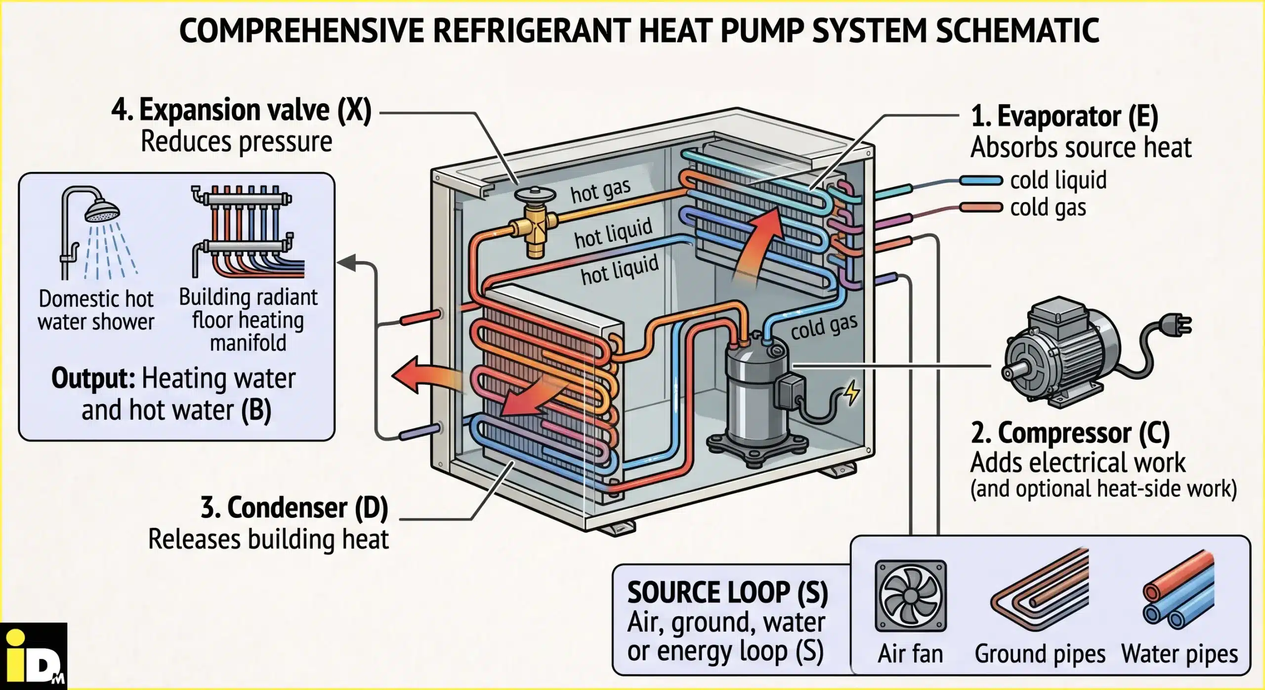
How do pressure and phase change make heat transfer possible?
Pressure sets the temperature at which refrigerant evaporates or condenses. Low pressure lets it boil below the heat-source temperature; high pressure lets it condense above the heating-water temperature. These saturation temperatures establish the direction of heat transfer in each exchanger.
Saturation temperature is the boiling or condensing temperature associated with a specific pressure. The evaporating pressure is controlled so the refrigerant remains colder than the heat source. Heat then flows from air, ground, water or a shared energy loop into the refrigerant.
Compression establishes the high-pressure side. The resulting condensing temperature must exceed the heating-water temperature, allowing energy to flow from refrigerant to water. A larger separation between source and heating temperatures requires more compressor work.
Phase change transfers substantial energy without requiring an equally large refrigerant-temperature change. The refrigerant absorbs latent heat while evaporating and releases latent heat while condensing. Latent heat is energy associated with a change between liquid and vapour.
Refrigerant chemistry determines the pressures, temperatures, environmental characteristics and safety requirements available to the designer.
Where does the delivered heat energy come from?
A heat pump delivers more heat than the electricity it uses because electricity drives heat transfer instead of supplying all output directly. Delivered heat equals environmental heat absorbed at the source plus electrical work supplied to the compressor during operation.
The heating energy balance is:
Qheating is heat delivered to the heating circuit. Qsource is heat absorbed from air, ground, water or another source. Welectric is electrical work supplied to the compressor within this simplified boundary.
Fans, circulation pumps, controls and backup heating also use electricity. A performance figure must state whether these auxiliary inputs are included; otherwise, two apparently identical ratios may represent different system boundaries.
A hypothetical system that supplies 12,000 kWh of heat with an annual performance factor of 4.0 requires approximately 3,000 kWh of electricity within the stated boundary. The remaining 9,000 kWh is transferred from the source. This calculation illustrates energy balance rather than predicting a specific installation.
Why does temperature lift determine cycle efficiency?
Temperature lift is the gap between the heat-source temperature and the required heating-water temperature. A smaller lift reduces compressor work and raises seasonal efficiency, so lower flow temperatures, adequate emitters, correct sizing, and stable heat sources materially improve overall performance.
Flow temperature is the temperature of water leaving the heat pump for the building's heat emitters. A cycle producing 35°C water from a given source requires less temperature lift than the same cycle producing 55°C water from that source.
Austria's 2026 klimaaktiv guide to good heat-pump installation states that reducing flow temperature by 5°C improves the annual performance factor, or JAZ, by approximately 10% to 15%. This planning rule is not a product guarantee because climate, hot-water demand, system boundaries and installation quality affect measured performance.
The ideal heating-cycle limit expresses the same relationship. Using absolute temperatures in kelvin, the Carnot heating COP is:
Real cycles remain below the Carnot limit because compressors, heat exchangers, pressure drops and auxiliary devices introduce losses. The equation explains why a smaller temperature difference helps; it does not forecast annual electricity use.
How do COP, SCOP and JAZ describe thermodynamic performance?
COP measures heat output divided by electrical input at one defined operating point. SCOP represents standardized seasonal performance, while Austria's Jahresarbeitszahl, or JAZ, describes annual performance under site conditions and depends on the chosen measurement boundary and auxiliary electricity use.
Coefficient of Performance (COP) is a dimensionless ratio:
A COP of 4 means four units of heat are delivered per unit of electrical input under the stated test conditions. The ratio does not mean energy was created; approximately three units were transferred from the source.
Seasonal Coefficient of Performance (SCOP) combines standardized temperatures and loads across a defined heating season. SCOP supports product comparisons made under the same standard, but actual building operation can differ.
Jahresarbeitszahl (JAZ) relates delivered heat to consumed electricity under site conditions over an annual period. The measurement boundary determines which pumps, fans, backup heating and hot-water loads are included.
| Metric | Boundary in time | Appropriate use | Required context |
|---|---|---|---|
| COP | One test point | Compare performance at identical source and water temperatures | Test temperatures, load and included electrical inputs |
| SCOP | Standardized season | Compare products under the same calculation standard | Climate profile, water-temperature application and standard |
| JAZ | Predicted or measured year at one site | Estimate or verify installed seasonal performance | System boundary, building demand, hot water and auxiliary electricity |
How does iDM apply the same cycle across its product families?
iDM applies the same heat-pump thermodynamics across product families configured for different sources, buildings, temperatures, and capacities. AERO uses outdoor air; TERRA uses ground or water; iPUMP integrates storage; MAX scales output; NANO serves decentralized apartment applications in multi-storey renovations.
Product configuration changes the source interface, capacity, storage arrangement and intended application. The underlying sequence—evaporation, compression, condensation and expansion—remains the same.
| iDM family | System context | Connection to cycle thermodynamics |
|---|---|---|
| AERO – Air Source Heat Pumps | Outdoor-air source | Source temperature varies with weather, changing evaporating conditions and temperature lift |
| TERRA – Geothermal Heat Pumps | Ground or groundwater source | A steadier source supports more stable evaporating conditions |
| iPUMP heat pumps with hot water tank | Integrated heat pump and hot-water storage | Storage changes packaging and demand timing, not the four-stage cycle |
| MAX – Large Heat Pumps | Large-building and commercial systems | Multiple circuits or cascaded units repeat the same energy balance at greater capacity |
| NANO – iDM THERMEPUMPE | Decentralized apartment systems connected to a shared low-temperature source | Each dwelling’s cycle raises shared source heat to a useful local temperature |
These family descriptions show how each system relates to the same thermodynamic cycle. They do not replace product selection or current technical datasheets. Capacity, temperature, refrigerant and availability must be verified for the specific model and country during system design.
What are the key thermodynamic-cycle FAQs?
The following questions clarify terminology. They distinguish a thermodynamic cycle from individual components, explain why refrigerant circulates rather than being consumed, and show why theoretical performance cannot predict one building’s annual electricity use.
Is a refrigeration cycle different from a heat-pump cycle?
No. Both terms can describe the same vapour-compression cycle. The useful effect determines the name: refrigeration values heat removed from a cold space, while heating values heat released at the condenser.
What is the difference between the cycle and “how a heat pump works”?
The thermodynamic cycle describes refrigerant states and energy transfers inside the sealed circuit. A complete operating explanation also covers the environmental source, pumps or fans, controls, heating water, storage, emitters and the building. See How Heat Pumps Work for that wider system view.
Is refrigerant consumed during every cycle?
No. Refrigerant circulates repeatedly inside a closed circuit. Normal operation changes its pressure, temperature and phase without consuming it. Leakage is an abnormal condition that requires qualified inspection; refrigerant safety and environmental properties are covered under Heat Pump Refrigerants.
Is COP the same as percentage efficiency?
No. COP is a heat-output-to-electric-input ratio. A COP above 1 is possible because the output includes source heat plus compressor work. It is not a conventional conversion-efficiency percentage and does not exceed conservation-of-energy limits.
Can the Carnot COP predict a household electricity bill?
No. Carnot COP is an ideal thermodynamic limit. Real electricity use depends on weather, flow temperatures, part-load operation, hot-water demand, auxiliaries, controls and installation quality. A site-specific seasonal estimate and measured JAZ provide more relevant evidence.
What is the next step from thermodynamics to system design?
Thermodynamic understanding narrows the purchasing question to the operating conditions that matter: source temperature, required flow temperature, seasonal load, and system boundary. A qualified design must then match those conditions to the building, heat source, emitters, controls, and iDM configuration.
Use the iDM configurator for initial orientation in a single- or two-family home. A qualified partner must then confirm the design heat load, available source, required water temperatures and intended services. NANO, MAX and other complex projects require project-specific consultation.